I have described the integration of the LEDs in a previous post, now we focus on all of the other electronic components needed to make it work.
There is very limited space inside my model and as I want to make everything completely invisible, a little bit of creativity is needed.
Battery and Battery-Charging
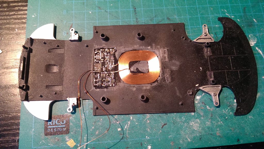
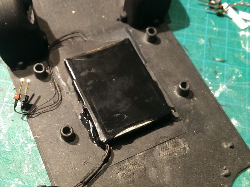
I chose a Li-Ion battery for power supply. The only good place for it is inside the gap between the cockpit and the underbody. I want no connectors to be visible after the model is finished, so I integrated a wireless charging coil into the underbody before gluing the battery pack on it. These coils can be bought from eBay pretty cheap. They are originally designed for upgrading your phone and contain everything on the electronics side. Output of the black PCB is 5V DC. Just like what you get from a regular USB charger.
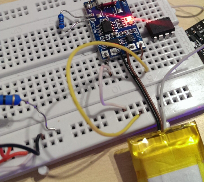
Charging of the Li-Ion battery pack is managed by one of those blue PCBs you can buy on eBay. They have the TP4056 chip on them. It regulates the charge voltage and current. Further, the battery needs to be protected from under discharge (low output voltage). The charger PCB has this feature integrated. It disconnects the load from the battery if the voltage is too low.
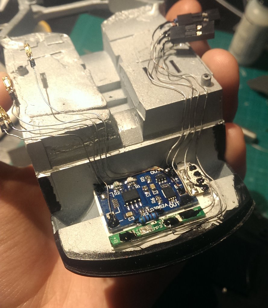
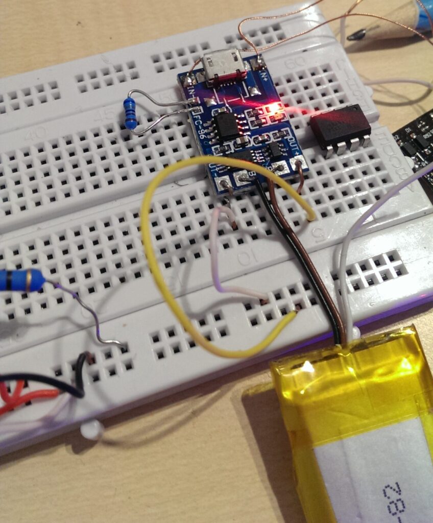
However, the cutoff voltage of the integrated protection is too low for my taste. A fully charged battery is at 4.2V and the nominal voltage at which the battery will operate most of the time is 3.7V. If the battery falls below 3.5V, not much charge is left and the voltage will rapidly decrease if nothing is done. The voltage should never fall below 3V. The protection has a cutoff voltage of around 2.8V-3V. It is better to set this point a little bit higher, so I bought another protection PCB (green) which has this point at around 3.3V. This is also the minimal voltage I want to apply to the microcontroller. This should conserve the battery much better and extend its life. On the other hand not much capacity is lost.
The battery charging electronics will be placed directly behind the cockpit as high as possible. The gearbox will be directly underneath it.
Microcontroller
A microcontroller will drive the LEDs. I preffered to use the Arduino environment for programming. This limits the usable microcontrollers for a beginner like me to a handful of Atmel 8-bit AVRs. I chose an Attiny84 as main MCU. After testing on a breadboard I made a layout for a PCB with the Fritzing software and ordered it. The Attiny uses its internal clock and so the external parts are at an absolute minimum. Only resistors and transistors are additionally needed for driving the LEDs.
Communication between the user and the model is possible in multiple ways. Radio control (RF), Bluetooth, infrared (IR) and even WiFi are possible. I don’t want an own controller or remote for it, so I chose Bluetooth. Implementation of Bluetooth is very easy as boards like the HC-06 exist and can be embedded into the system without further modifications. It communicates over UART with the MCU. UART is natively supported by the bigger Atmels, but can be integrated to the Attinys over software. The Arduino IDE makes that very easy.
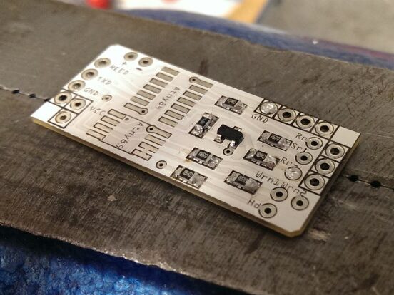
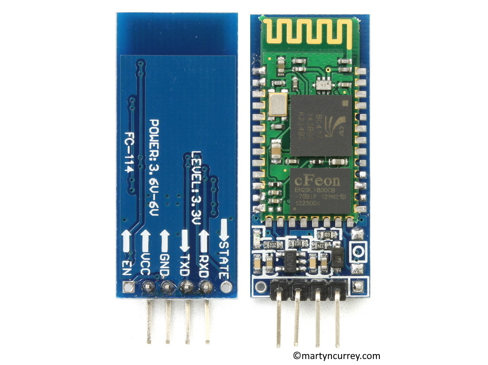
The size of the PCB equals the shape and size of the HC-06. The two will be soldered together and connected to the rest of the electronics.
The main PCB and Bluetooth module will be placed inside the trunk.
Power Switch
The power switch for the whole system caused some headaches. I don’t want a switch to be visible but also don’t want the microcontroller to be in sleep mode all the time. The model may stand on the shelf for long times between operations. In this time I don’t want the battery to drain and eventually hit the 3.3V threshold. Staying there for very long times may cause damage to the battery.
The solution is a relais. It’s a mechanical switch and in the form of a reed-relais it can be activated using a magnet. But this isn’t enough, because with the absence of the magnet the switch would open again. This is not the case for reed-relais with an integrated coil such as the SIL05-1A72-71D.
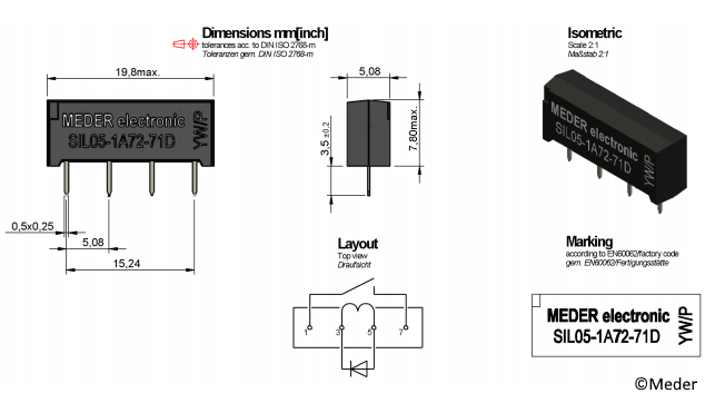
The coil can replace the magnet by generating a magnetic field around the switch. After initial activation with the magnet, the MCU can drive the coil and thus keep the switch activated. Switching off the electronics can then theoretically only be done in code. The switch will be placed as far in the back as possible to activate it by nearing the magnet to the rear of the car.
Everything Connected
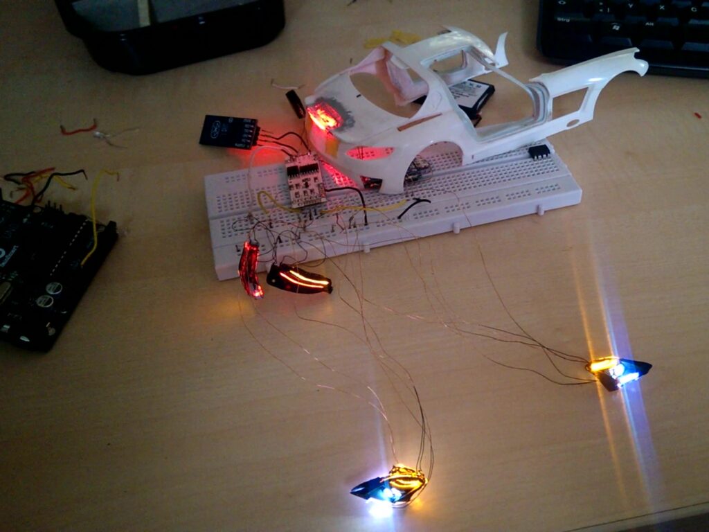
– Project Page –